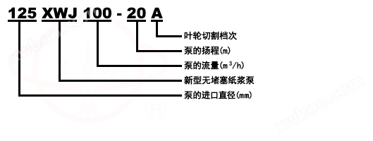
Model Meaning

Product Introduction
XWJ non clogging pulp pump is a new and energy-saving pulp pump. Through practical use, it has the characteristics of high efficiency, no or less leakage, good anti clogging, smooth operation, high reliability, and compact structure. This is mainly reflected in the following aspects: the use of semi open or fully open impellers, adjustable clearance between the wear-resistant plate and the front side of the impeller, mechanical seals are mainly used for shaft seals, and high-precision bearings (D-level precision) and high-quality shaft materials are selected
STRUCTURE DESCRIPTION
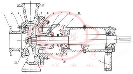
1. The XWJ unobstructed pulp pump is a single-stage single suction cantilever structure, mainly composed of a pump body, impeller, pump cover, wear-resistant plate, and suspension components
2. From the motor end, the motor rotates clockwise, and the pump sucks in axially and discharges radially (between φ)
3. The pump has a rear opening structure, so there is no need to disassemble the inlet and outlet pipelines during maintenance
4. The pump shaft is supported by two high-precision rolling bearings and lubricated with thin oil (20 supports of engine oil)
5. The shaft seal adopts two types: mechanical seal or packing
6. The clearance between the wear-resistant plate and the front side of the impeller can be adjusted by adjusting the screw to maintain the high efficiency of continuous operation of the impeller
7. The pump and motor are directly driven by a pin coupling.
The material of each overcurrent component of the pump is HT200, QT450-10, ZG35 or ZG1Cr18Ni9Ti, and the shaft material is 40Cr or 3Cr13.
application
XWJ non clogging pulp pump can be widely used in the transportation of pulp with temperature below 110 ℃ and concentration below 6% in the light industry and papermaking industry. It can also be used in industrial and urban water supply, drainage and other occasions
Structure diagram
 |
1 |
pump body |
7 |
hose connector |
2 |
adjusting screw |
8 |
Packing or mechanical seal |
|
3 |
wear plate |
9 |
County frame components |
|
4 |
impeller |
10 |
bracket |
|
5 |
O-rings |
11 |
water deflector |
|
6 |
pump cover |
12 |
IMPELLER NUT |
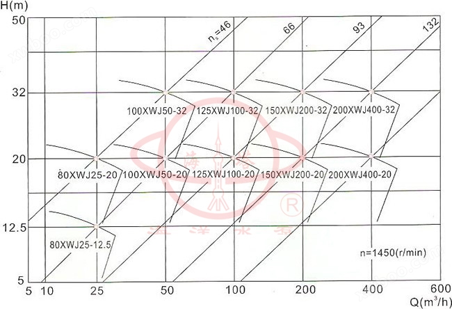
performance parameter
Pump model |
internet traffic (m3/h) |
lift (m) |
rotational speed (r/min) |
Supporting motor model and power (KW) |
80XWJ25-12.5 |
25 |
12.5 |
1450 |
Y100L1-4/2.2 |
80XWJ25-12.5A |
20 |
10 |
1450 |
Y90l-4/1.5 |
80XWJ25-20 |
25 |
20 |
1450 |
Y100L2-4/3 |
80XWJ25-20A |
20 |
16 |
1450 |
Y100L-4/2.2 |
100XWJ50-20 |
50 |
20 |
1450 |
Y132S-4/5.5 |
100XWJ50-20A |
45 |
18 |
1450 |
Y112M-4/4 |
100XWJ50-20B |
40 |
16 |
1450 |
Y112M-4/4 |
100XWJ50-32 |
50 |
32 |
1450 |
Y160M-4/11 |
100XWJ50-32A |
40 |
26 |
1450 |
Y132S-4/5.5 |
125XWJ100-20 |
100 |
20 |
1450 |
Y160M-4/11 |
125XWJ100-20A |
90 |
18 |
1450 |
Y132S-4/7.5 |
125XWJ100-20B |
80 |
16 |
1450 |
Y132S-4/7.5 |
125XWJ100-32 |
100 |
32 |
1450 |
Y160M-4/15 |
125XWJ100-32A |
90 |
28 |
1450 |
Y160M-4/11 |
125XWJ100-32B |
80 |
26 |
1450 |
Y160M-4/11 |
150XWJ200-20 |
200 |
20 |
1450 |
Y180M-4/18.5 |
150XWJ200-20A |
180 |
18 |
1450 |
Y160M-4/15 |
150XWJ200-20B |
160 |
16 |
1450 |
Y160M-4/11 |
150XWJ200-32 |
200 |
32 |
1450 |
Y200L-4/30 |
150XWJ200-32A |
187 |
28 |
1450 |
Y180M-4/22 |
150XWJ200-32B |
170 |
24 |
1450 |
Y180M-4/18.5 |
200XWJ400-20 |
400 |
20 |
1450 |
Y225S-4/37 |
200XWJ400-20A |
380 |
18 |
1450 |
Y200L-4/30 |
200XWJ400-20B |
340 |
15 |
1450 |
Y180L-4/22 |
200XWJ400-32 |
400 |
32 |
1450 |
Y250M-4/55 |
200XWJ400-32A |
375 |
28 |
1450 |
Y225M-4/45 |
200XWJ400-32B |
340 |
24 |
1450 |
Y225S-4/37 |
Note: The experimental medium is clean water at room temperature |
||||
Type Understanding Diagram
 |
instructions
1. Before starting the pump, it should be inspected according to the following requirements;
1.1. Have all bolts been tightened; Has thin oil been injected into the bearing chamber (with the oil level at the center of the oil gauge)
1.2. Is the coaxiality of the coupling less than or equal to a small diameter of 0.3mm? At the same time, rotating the coupling by hand should feel easy and even
1.3. Whether the motor direction is correct
1.4. Is the imported valve fully open
1.5. Is the outlet valve closed
1.6. Whether the sealing water valve is open; Sealing water pressure requirement: working pressure plus (0.3~0.5) kgf/c
2. After starting the motor to its rated speed, slowly open the outlet valve to the required rated operating condition (with the motor operating current at 80% of the rated value).
3. During the operation of the pump, attention should be paid to the stability of the pump and the cooling and flushing of the sealing water.
4. When the pump runs for a period of time or the head decreases, attention should be paid to adjusting the clearance on the front side of the impeller. The adjustment method is as follows: first loosen each fastening nut, rotate the square head adjustment screw (see structural diagram) counterclockwise until the wear-resistant plate collides with the front side of the impeller, and then retract the square head adjustment screw clockwise to 1/2 turn (at this time, the clearance is 0.8-1mm), and then tighten each nut.
5. When the pump stops running, the outlet valve should be closed first, and then the motor power should be turned off.
6. When the pump needs to be stopped for a period of time, the accumulated fluid in the pump should be drained for the next use.
Drawing
 |
|||||||||||||
Pump model |
Supporting motor model and power (kw) |
A |
L1 |
L2 |
L3 |
a |
L4 |
L5 |
B1 |
B |
H1 |
H |
n-d |
80XWJ25-12.5 |
Y100L1-4/2.2 |
60 |
768 |
108 |
550 |
110 |
371 |
847 |
310 |
350 |
215 |
425 |
4-Φ18 |
80XWJ25-12.5A |
Y90L-4/1.5 |
60 |
768 |
108 |
550 |
110 |
371 |
807 |
310 |
350 |
215 |
425 |
4-Φ18 |
80XWJ25-20 |
Y100L2-4/3 |
110 |
980 |
120 |
740 |
125 |
491 |
847 |
440 |
490 |
255 |
490 |
4-Φ18 |
80XWJ25-20A |
Y100L1-4/2.2 |
110 |
980 |
120 |
740 |
125 |
491 |
847 |
440 |
490 |
255 |
490 |
4-Φ18 |
100XWJ50-20 |
Y132S-4/1.5 |
90 |
920 |
130 |
660 |
125 |
472 |
1077 |
440 |
490 |
270 |
520 |
4-Φ18 |
100XWJ50-20A |
Y112M-4/4 |
90 |
920 |
130 |
660 |
125 |
472 |
1002 |
440 |
490 |
270 |
520 |
4-Φ18 |
100XWJ50-20B |
Y112M-4/4 |
90 |
920 |
130 |
660 |
125 |
472 |
1002 |
440 |
490 |
270 |
520 |
4-Φ18 |
100XWJ50-32 |
Y160M-4/11 |
90 |
1043 |
125 |
740 |
125 |
472 |
1207 |
460 |
510 |
300 |
580 |
4-Φ18 |
100XWJ50-32A |
Y132S-4/5.5 |
90 |
990 |
125 |
740 |
125 |
472 |
1077 |
460 |
510 |
300 |
580 |
4-Φ18 |
125XWJ100-20 |
Y160M-4/11 |
90 |
1200 |
180 |
840 |
140 |
502 |
1252 |
460 |
510 |
300 |
580 |
4-Φ24 |
125XWJ100-20A |
Y132M-4/7.5 |
90 |
990 |
125 |
740 |
140 |
502 |
1162 |
460 |
510 |
300 |
580 |
4-Φ18 |
125XWJ100-20B |
Y132M-4/7.5 |
90 |
990 |
125 |
740 |
140 |
502 |
1162 |
460 |
510 |
300 |
580 |
4-Φ18 |
125XWJ100-32 |
Y160L-4/15 |
90 |
1200 |
180 |
840 |
140 |
502 |
1297 |
460 |
510 |
325 |
640 |
4-Φ24 |
125XWJ100-32A |
Y160M-4/11 |
90 |
1200 |
180 |
840 |
140 |
502 |
1252 |
460 |
510 |
325 |
640 |
4-Φ24 |
125XWJ100-32B |
Y160M-4/11 |
90 |
1200 |
180 |
840 |
140 |
502 |
1252 |
460 |
510 |
325 |
640 |
4-Φ24 |
150XWJ200-20 |
Y180M-4/18.5 |
90 |
1200 |
180 |
840 |
150 |
502 |
1327 |
460 |
510 |
325 |
680 |
4-Φ24 |
150XWJ200-20A |
Y160L-4/15 |
90 |
1200 |
180 |
840 |
150 |
502 |
1307 |
460 |
510 |
325 |
680 |
4-Φ24 |
150XWJ200-20B |
Y160M-4/11 |
90 |
1200 |
180 |
840 |
150 |
502 |
1262 |
460 |
510 |
325 |
680 |
4-Φ24 |
150XWJ200-32 |
Y200L-4/30 |
90 |
1200 |
180 |
840 |
150 |
502 |
1432 |
460 |
510 |
375 |
730 |
4-Φ24 |
150XWJ200-32A |
Y180L-4/22 |
90 |
1200 |
180 |
840 |
150 |
502 |
1367 |
460 |
510 |
375 |
730 |
4-Φ24 |
150XWJ200-32B |
Y180M-4/18.5 |
90 |
1200 |
180 |
840 |
150 |
502 |
1327 |
460 |
510 |
375 |
730 |
4-Φ24 |
200XWJ400-20 |
Y225S-4/37 |
115 |
1500 |
200 |
1050 |
350 |
652 |
1487 |
630 |
690 |
465 |
865 |
4-Φ28 |
200XWJ400-20A |
Y200L-4/30 |
115 |
1500 |
200 |
1050 |
350 |
652 |
1442 |
630 |
690 |
465 |
865 |
4-Φ28 |
200XWJ400-20B |
Y180L-4/22 |
115 |
1500 |
200 |
1050 |
350 |
652 |
1377 |
630 |
690 |
465 |
865 |
4-Φ28 |
200XWJ400-32 |
Y250M-4/55 |
115 |
1500 |
200 |
1050 |
350 |
652 |
1717 |
630 |
690 |
465 |
865 |
4-Φ28 |
200XWJ400-32A |
Y225M-4/45 |
115 |
1500 |
200 |
1050 |
350 |
652 |
1632 |
630 |
690 |
465 |
865 |
4-Φ28 |
200XWJ400-32B |
Y225S-4/37 |
115 |
1500 |
200 |
1050 |
350 |
652 |
1607 |
630 |
690 |
465 |
865 |
4-Φ28 |
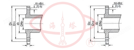
Flange dimension diagram
 |
||||||||||||
Pump model |
Imported flange size |
Export flange size |
||||||||||
DN1 |
D1 |
D11 |
d1 |
b1 |
n1-d01 |
DN2 |
D2 |
D12 |
d2 |
b2 |
n2-d02 |
|
80XWJ25-12.5 |
80 |
190 |
150 |
128 |
18 |
4-Φ18 |
65 |
160 |
130 |
110 |
16 |
4-Φ18 |
80XWJ25-20 |
80 |
190 |
150 |
128 |
18 |
4-Φ18 |
65 |
160 |
130 |
110 |
16 |
4-Φ18 |
100XWJ50-20 |
100 |
210 |
170 |
148 |
18 |
4-Φ18 |
80 |
190 |
150 |
128 |
18 |
4-Φ18 |
100XWJ50-32 |
100 |
210 |
170 |
148 |
18 |
4-Φ18 |
80 |
190 |
150 |
128 |
18 |
4-Φ18 |
125XWJ100-20 |
125 |
240 |
200 |
178 |
20 |
8-Φ18 |
100 |
210 |
170 |
148 |
18 |
4-Φ18 |
125XWJ100-32 |
125 |
240 |
200 |
178 |
20 |
8-Φ18 |
100 |
210 |
170 |
148 |
18 |
4-Φ18 |
150XWJ200-20 |
150 |
265 |
225 |
202 |
20 |
8-Φ18 |
125 |
240 |
200 |
178 |
20 |
8-Φ18 |
150XWJ200-32 |
150 |
265 |
225 |
202 |
20 |
8-Φ18 |
125 |
240 |
200 |
178 |
20 |
8-Φ18 |
200XWJ400-20 |
200 |
320 |
280 |
258 |
22 |
8-Φ18 |
150 |
265 |
225 |
202 |
20 |
8-Φ18 |
200XWJ400-32 |
200 |
320 |
280 |
258 |
22 |
8-Φ18 |
150 |
265 |
225 |
202 |
20 |
8-Φ18 |

