|
Product Overview/Product overview----------------------------------------------------------◆◆
|
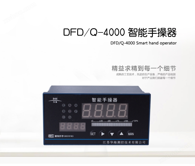
| The DFD/Q-4000 series intelligent operator is an intelligent instrument that can replace the servo amplifier and two instruments in traditional DDZ automation control systems. Adopting on-chip system technology, with a single structure, superior performance, reliable quality, dual digital light column triple display, beautiful and eye-catching, it can be used in conjunction with various intelligent regulators or DCS computer control systems at home and abroad as a backup manual output unit for host failures and maintenance. |
| |
| This series of instruments is divided into D-type operation, Q-type operation, and hard hand operation. |
| D-type handheld device |
| D-type manual controller is a device that calculates the control signal transmitted by the regulator or DCS and the valve position signal feedback from the actuator, and directly outputs forward and reverse electrical signals to drive the motor of the electric actuator. It controls the forward and reverse rotation of the motor and outputs the valve position signal to the regulator. When the operator switches from automatic to manual mode, the status signal of the switch quantity is output to the regulator as the valve position tracking signal. That is, when the regulator receives the manual status signal from the operator, it tracks the valve position. |
| |
| ◆ Q-type handheld device |
| A Q-type operator is a device that calculates the valve position signal from a regulator or DCS and feedback from an actuator, and outputs a linear current or voltage signal to directly drive the pneumatic valve, control the opening and closing of the valve, and output the valve position signal to the regulator. When the operator switches from automatic to manual mode, the status signal of the switch quantity is output to the regulator as the valve position tracking signal. That is, when the regulator receives the manual status signal from the operator, it tracks the valve position. |
| |
| ◆ Hard hand operation |
| Hard hand operation is an operator without automatic control, which only receives valve position signals and controls output through human-machine dialogue. The output signals can be forward and reverse electrical signals (D-type hard hand operation) or linear current and voltage signals (Q-type hard hand operation). Receive the valve position signal and display the valve position to determine the valve opening. |
Performance Features/performance function-----------------------------------------------------◆◆
|
| 1. The input signal can be arbitrarily specified and selected. |
| 2. Power on automatically or manually (manual output value can be preset). |
| 3. Hand automatic state output. |
| 4. Triple display of process quantity indication, control quantity indication, valve position feedback indication, etc. |
| 5. The upper and lower output ranges can be set separately. |
| 6. Simulated output of valve position feedback value. |
| 7. Control quantity analog output. |
| 8. EM1- Remote manual function, the initial output value remains unchanged. After canceling the remote manual function, it can remain in manual mode or return to automatic mode. |
| 9. EM2 has a remote manual function, and the initial output value can be preset. |
| 10. Valve position feedback error indication, valve position feedback disconnection can automatically enter manual mode. |
| 11. Tracking error error indication. |
| 12. When the main input is disconnected, the control signal will automatically protect the motor (which can be manually operated) and output a fault alarm signal. |
| 13. The instrument is equipped with two 40A bidirectional thyristors, which directly control the forward and reverse rotation of the motor of the actuator. |
| 14. This instrument can also be equipped with a single position control instrument (universal input). The signal input of the handheld device is used for calibration, and the positional instrument is calibrated using the E menu. |
Product selection/product selection------------------------------------------------------------◆◆
|
| DF |
Remarks |
| Instrument type |
D |
Electric hand controller |
| Q |
Pneumatic manipulator |
| Design sequence |
4 |
4000 series instrument |
| Display mode |
1 |
Single screen+dual light pillar |
| 2 |
Dual screen+single light column |
| 3 |
Dual screen+dual light pillar |
| 4 |
Three screen display |
| Input method |
1 |
Equipped with DC current (0~10mA, 4~20mA) |
| 2 |
Equipped with DC voltage (0~5V, 1~5V) |
| 3 |
Special input signal ordering instructions |
|
Control output and
Adjustment method
|
Electric hand controller |
1 |
Forward and reverse rotation+upper and lower limit alarms |
| 2 |
Forward rotation, reverse rotation+manual output |
| 3 |
Forward and reverse rotation+EM1 function |
| 4 |
Forward and reverse rotation+EM2 function |
| 5 |
Forward and reverse rotation+manual power on function |
| 6 |
Forward and reverse rotation+lower and lower limit amplitude limiting function |
| Pneumatic manipulator |
1 |
Output DC (0~10mA, 4~20mA)+upper and lower limit alarms |
| 2 |
Output DC (0~10mA, 4~20mA)+manual output |
| 3 |
Output DC (0~10mA, 4~20mA)+EM1 function |
| 4 |
Output DC (0~10mA, 4~20mA)+EM2 function |
| 5 |
Output DC (0~10mA, 4~20mA)+manual startup function |
| 6 |
Output DC (0~10mA, 4~20mA)+upper and lower limit limiting function |
| Valve position feedback input method |
0 |
No valve position feedback |
| 1 |
Feedback 0~10mA |
| 2 |
Feedback 4-20mA |
| 3 |
Feedback 0~5V |
| 4 |
Feedback 1-5V |
| 5 |
Feedback 0~10V |
| 6 |
Feedback potentiometer (indicate resistance value when ordering) |
| DF |
Remarks |
| External dimensions |
H |
Horizontal 160 × 80 |
Opening 152 × 76 |
| V |
Horizontal 80 × 160 |
Opening 76 × 152 |
| F |
Method 96 × 96 |
Opening 92 × 92 |
| Q |
Method 72 × 72 |
Hole 68 × 68 |
| Valve position feedback value transmission output |
A |
No transmission output |
| B |
Transmission output 0~10mA |
| C |
Transmission output 4~20mA |
| D |
Transmission output 0~5V |
| E |
Transmission output 1~5V |
| F |
Special signal transmission output (specified in order) |
| Control quantity transmission output |
a |
No transmission output |
| b |
Transmission output 0~10mA |
| c |
Transmission output 4~20mA |
| d |
Transmission output 0~5V |
| e |
Transmission output 1~5V |
| f |
Special signal transmission output (specified in order) |
| Supply external 24V DC current |
P |
Default is no 24V DC power output |
| With 24V DC power output (can be used as a two-wire transmitter power supply) |
| communication interface |
T |
Default is without communication interface |
| Equipped with RS485 or RS232 communication interface |
| power supply |
K
W
|
Default is 220V. AC |
| Switching power supply 85~260VAC |
| Switching power supply 18~36VDC or 18~36VAC |
|
Technical indicators/Technical indicators---------------------------------------------------------◆◆
|
| 1. Measurement accuracy: ± 0.5% FS+1d ± 0.2% FS+1d |
| 2. Analog output accuracy: valve position feedback output ± 0.5% FS, control quantity output ± 0.5% FS |
| 3. Analog output driving load impedance: Current signal: 0~10mA ≥ 1.5K Ω; 4~20mA ≥ 750 Ω. Voltage signal: 0~5V, 1~5V Output impedance ≤ 1 Ω |
| 4. Analog input impedance: current signal: ≤ 50 Ω; Voltage signal: ≥ 500K Ω |
| 5. Manual/automatic status output: Automatic status is off; Manual status is on |
| 6. Remote manual input EM1: Low level connection, EM1 energy is effective, disconnection is ineffective. Remote manual input of EM2: Low level connection, EM2 energy is effective, disconnection is ineffective. |
| 7. Relay contact capacity: AC220V, 3A (resistive load) |
| 8. The parameter retention time set after the instrument is powered off: ≥ 20 years |
| 9. Insulation strength: AC voltage 1500V, 1 minute |
| 10. Insulation impedance: above 50M Ω |
| 11. Power supply: 220V, 50HZ, ≤ 6W or 24V |
| 12. Work environment requirements: temperature 0-50 ℃, relative humidity: ≤ 85%, no corrosive gases, no vibration. |
|
Display description----------------------------------------------------------◆◆
|
| 1. Dual screen display |
| The upper digital display shows the adjustment amount of the upper computer, and when entering the parameter setting mode, it displays a prompt for setting parameters. |
| ★ The lower digital display shows the percentage of control quantity or valve position feedback quantity (please specify when ordering). When in manual mode, display the manual output control quantity in percentage form. When entering the parameter setting mode, display the set parameters. |
| 2. Dual screen+single analog strip |
| The upper digital display shows the adjustment amount of the upper computer, and when entering the parameter setting mode, it displays a prompt for setting parameters. |
| ★ The lower digital display shows the percentage of control quantity or valve position feedback quantity (please specify when ordering). When in manual mode, display the manual output control quantity in percentage form. When entering the parameter setting mode, display the set parameters. |
| The analog bar displays the percentage of valve position feedback. |
| 3. Single screen+dual-mode strip simulation |
| The digital display shows the adjustment amount of the upper computer, or displays the valve position feedback signal in percentage form, or displays the control amount in percentage form. Use the plus key to switch the display mode. When in manual mode, display the manual output control quantity in percentage form. When entering the parameter setting mode, alternately display the prompt for setting parameters and the setting parameters. |
| The left analog bar displays the control quantity of the output signal of the upper computer or regulator in percentage form. |
| The right analog bar displays the valve position feedback in percentage form. |
| 4. Dual screen+dual-mode strip simulation |
| The upper digital display shows the adjustment amount of the upper computer, and when entering the parameter setting mode, it displays a prompt for setting parameters. |
| ★ The lower digital display shows the percentage of control quantity or valve position feedback quantity (please specify when ordering). When in manual mode, display the manual output control quantity in percentage form. When entering the parameter setting mode, display the set parameters. |
| The left analog bar displays the control quantity of the output signal of the upper computer or regulator in percentage form. |
| The right analog bar displays the valve position feedback in percentage form. |
| 5. Three screen display |
| The upper digital display shows the adjustment amount of the upper computer, and when entering the parameter setting mode, it displays a prompt for setting parameters. |
| ★ The middle row digital display shows the percentage of valve position feedback. When in manual mode, display the manual output control quantity in percentage form. When entering the parameter setting mode, display the set parameters. |
| ★ The lower digital display shows the percentage of control quantity. |
| 6. Indicator light |
| The A light is a forward rotation indicator light (DFD) or a control quantity and valve position feedback positive deviation alarm indicator light (DFQ). |
| The E light is a reverse indicator light (DFD) or a control quantity and valve position feedback negative deviation alarm indicator light (DFQ) |
| The C light is an automatic indicator light or SP4 alarm indicator light. |
| The G light is a manual indicator light. |
| B light is the SP3 alarm indicator light. |
| The D light is the EM1 status indicator light. |
| The F light is the EM2 status indicator light. |
|
Instrument wiring/Instrument wiring-----------------------------------------------------------◆◆
|
| TABLE I |
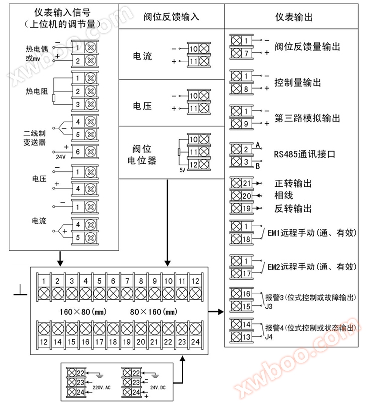 |
| Note: For differences between special orders and this wiring diagram, the random wiring diagram shall prevail. |
| |
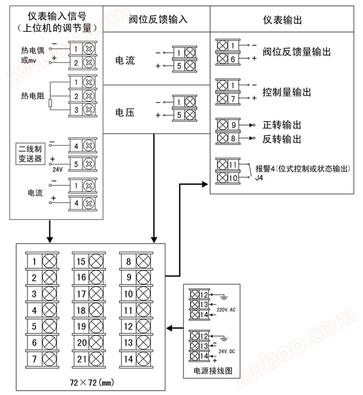
| Table 2 |
 |
| Note: For differences between special orders and this wiring diagram, the random wiring diagram shall prevail. |
| |
| Table III |
 |
| Note: For differences between special orders and this wiring diagram, the random wiring diagram shall prevail. |
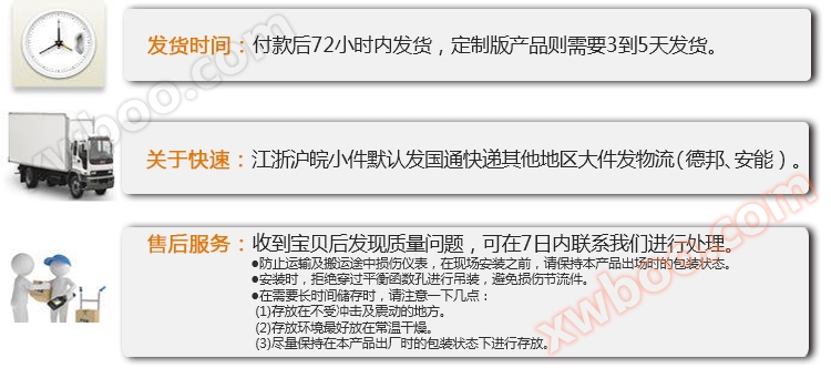
Usage and Maintenance/usage and maintenance--------------------------------------------------◆◆
|
| 1. The instrument should be placed in a dry, ventilated and non corrosive gas environment, and the ambient temperature and relative humidity should meet the technical conditions. |
| 2. Choose the appropriate instrument model and related programs as needed, so that users can use them without debugging or directly. |
| 3. Due to the multiple functions of the instrument, it is necessary to correctly set the menu operation program and wiring according to the working conditions. If necessary, it is recommended that the user send personnel to the manufacturer for learning. |
| 4. If the instrument is damaged due to quality issues with the manufacturer, it will be repaired free of charge by the manufacturer within one year. |
|
Product packaging/Product packaging----------------------------------------------------------◆◆
|
 |
Logistics Description/Logistics instructionss-------------------------------------------------------◆◆
|
 |
  |
 |
 |
 |
| |
| |
| |
| |
| |
| |
| |
| |
| |
| |

