
VIP member

GW unobstructed pipeline sewage pump
The GW unobstructed pipeline sewage pump is developed using advanced technology through absorption and conversion, and its performance indicators have
Product details
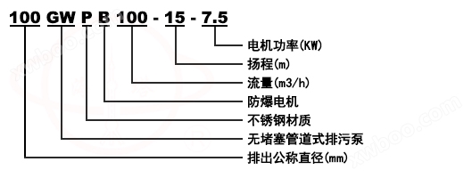
Model Meaning
Product Introduction
The GW unobstructed pipeline sewage pump is developed using advanced technology through absorption and conversion, and its performance indicators have reached the national standard for similar products. Due to the use of unique single (double) channel impellers, it has strong drainage capacity and can effectively pass through 5 times the diameter of the pump and solid particles with a diameter of 50% of the pump diameter. The dynamic seal adopts two sets of special hard alloy mechanical seal devices made of cast iron and stainless steel.
Product Features
The GW unobstructed pipeline sewage pump is a new type of pump designed using advanced technology based on the ISG vertical pipeline centrifugal pump. This pump can be used as a general pipeline pump for pressurized water delivery, as well as for pumping liquid impurities containing particles, fibers, suspended solids, and other impurities. It provides an ideal conveying machinery for industries such as chemical, textile, pharmaceutical, and environmental protection.
scope of application
The GW pipeline sewage pump is suitable for the discharge of severely polluted wastewater in factories and commercial areas, sewage discharge stations in main residential areas, water distribution systems in urban sewage treatment plants, drainage stations in civil air defense systems, water supply equipment in water plants, sewage discharge in hospitals and hotels, municipal engineering construction sites, mining auxiliary machinery, rural biogas digesters, farmland irrigation and other industries. It can also be used to transport granular sewage and pollutants, as well as clean water and weakly corrosive media.
application
1. The discharge of severely polluted wastewater from factories and commercial units.
2. Urban sewage treatment plant discharge system.
3. Sewage drainage system in residential areas.
4. Wastewater discharge from hospitals, hotels, and high-rise buildings.
5. Subway, basement, civil air defense system drainage station.
6. Discharge of slurry in municipal engineering and construction sites.
7. The water supply system of water companies and factories.
8. Wastewater discharge from breeding farms or rural biogas digesters, irrigation of farmland.
9. Exploration of mines and supporting equipment for water treatment.
10. Suitable for water supply and drainage in hydraulic engineering.
working conditions
A. The operating environment temperature of GW pipeline sewage pump is ≤ 40 ℃, and the humidity is ≤ 95%; Altitude ≤ 1000 meters.
B、 The medium temperature shall not exceed 60 ℃, and the medium density shall be 1-1.3kg/dm3.
C、 The range of use for cast iron material is from pH 5 to 9.
D、 Stainless steel material can be used with general corrosive media.
E、 The altitude of the usage environment should not exceed 1000 meters. If it exceeds the above conditions, it should be mentioned when placing an order to provide you with more reliable products.
Structure diagram
 |
1 |
electrical machinery |
2 |
Middle end cover |
|
3 |
pump body |
|
4 |
Waterproof ring |
|
5 |
mechanical seal |
|
6 |
impeller |
|
7 |
sealing ring |
performance parameter
model |
caliber |
internet traffic |
lift |
rotational speed |
power |
efficiency |
mm |
(m3/h) |
(M) |
(r/min) |
(kw) |
(%) |
|
25-7-8-0.55 |
25 |
7 |
8 |
2900 |
0.55 |
45 |
25-8-22-1.1 |
25 |
8 |
22 |
2900 |
1.1 |
45 |
32-8-12-0.75 |
32 |
8 |
12 |
2900 |
0.75 |
48 |
32-12-15-1.1 |
32 |
12 |
15 |
2900 |
1.1 |
45 |
40-15-15-1.5 |
40 |
15 |
15 |
2900 |
1.5 |
48 |
40-15-30-2.2 |
40 |
15 |
30 |
2900 |
2.2 |
54 |
50-20-7-0.75 |
50 |
20 |
7 |
2900 |
0.75 |
51 |
50-10-10-0.75 |
50 |
10 |
10 |
2900 |
0.75 |
52 |
50-20-15-1.5 |
50 |
20 |
15 |
290 |
1.5 |
53 |
50-15-25-2.2 |
50 |
15 |
25 |
2900 |
2.2 |
54 |
50-18-30-3 |
50 |
18 |
30 |
2900 |
3 |
55 |
50-40-15-4 |
50 |
40 |
15 |
2900 |
4 |
55 |
50-25-32-5.5 |
50 |
25 |
32 |
2900 |
5.5 |
55 |
50-20-40-7.5 |
50 |
50 |
20 |
2900 |
7.5 |
58 |
65-25-15-2.2 |
65 |
25 |
15 |
2900 |
2.2 |
50 |
65-37-13-3 |
65 |
37 |
13 |
2900 |
3 |
57 |
65-25-30-4 |
65 |
25 |
30 |
2900 |
4 |
61 |
65-30-40-7.5 |
65 |
30 |
40 |
2900 |
7.5 |
56 |
65-35-50-11 |
65 |
35 |
50 |
2900 |
11 |
45 |
65-35-60-15 |
65 |
35 |
60 |
2900 |
15 |
65 |
80-40-7-2.2 |
80 |
40 |
7 |
1450 |
2.2 |
59 |
80-43-13-3 |
80 |
43 |
13 |
2900 |
3 |
70 |
80-40-15-4 |
80 |
40 |
15 |
2900 |
4 |
61 |
80-60-13-5.5 |
80 |
60 |
13 |
2900 |
5.5 |
67 |
80-65-25-7.5 |
80 |
65 |
25 |
2900 |
7.5 |
63 |
model |
caliber |
internet traffic |
lift |
rotational speed |
power |
efficiency |
mm |
(m3/h) |
(M) |
(r/min) |
(kw) |
(%) |
|
100-80-10-4 |
100 |
100 |
10 |
1450 |
4 |
65 |
100-100-15-7.5 |
100 |
100 |
15 |
1450 |
7.5 |
68 |
100-80-20-7.5 |
100 |
80 |
20 |
1450 |
7.5 |
65 |
100-100-25-11 |
100 |
100 |
25 |
1450 |
11 |
70 |
100-100-30-15 |
100 |
100 |
30 |
1450 |
15 |
65 |
100-100-35-18.5 |
100 |
100 |
35 |
1450 |
18.5 |
68 |
125-130-15-11 |
125 |
130 |
15 |
1450 |
11 |
72 |
125-130-20-15 |
125 |
130 |
20 |
1450 |
15 |
75 |
150-145-9-7.5 |
150 |
145 |
9 |
1450 |
7.5 |
76 |
150-180-15-15 |
150 |
180 |
15 |
1450 |
15 |
69 |
150-180-20-18.5 |
150 |
180 |
20 |
1450 |
18.5 |
72 |
150-180-25-22 |
150 |
180 |
25 |
1450 |
22 |
78 |
150-130-30-22 |
150 |
130 |
30 |
1450 |
22 |
78 |
150-180-30-30 |
150 |
180 |
30 |
1450 |
30 |
78 |
150-200-30-37 |
150 |
200 |
30 |
1450 |
37 |
73 |
200-300-7-11 |
200 |
300 |
7 |
980 |
11 |
66 |
200-250-11-15 |
200 |
250 |
11 |
1450 |
15 |
64 |
200-250-15-18.5 |
200 |
250 |
15 |
1450 |
18.5 |
73 |
200-400-10-22 |
200 |
400 |
10 |
1450 |
22 |
75 |
200-400-13-30 |
200 |
400 |
13 |
14501 |
30 |
76 |
200-300-15-22 |
200 |
300 |
15 |
1450 |
22 |
76 |
200-250-22-30 |
200 |
250 |
22 |
1450 |
30 |
71 |
200-350-25-37 |
200 |
350 |
25 |
1450 |
37 |
71 |
200-400-30-45 |
200 |
400 |
30 |
1450 |
45 |
74 |
model |
caliber |
internet traffic |
lift |
rotational speed |
power |
efficiency |
mm |
(m3/h) |
(M) |
(r/min) |
(kw) |
(%) |
|
250-600-9-30 |
250 |
600 |
9 |
980 |
30 |
78 |
250-600-12-37 |
250 |
600 |
12 |
1450 |
37 |
76 |
250-600-15-45 |
250 |
600 |
15 |
1450 |
45 |
73 |
250-600-20-55 |
250 |
600 |
20 |
1450 |
55 |
73 |
250-600-25-75 |
250 |
600 |
25 |
1450 |
75 |
71 |
300-800-12-45 |
300 |
800 |
12 |
980 |
45 |
74 |
300-480-15-45 |
300 |
480 |
15 |
1450 |
45 |
66 |
300-800-15-55 |
300 |
800 |
15 |
1450 |
55 |
73 |
300-600-20-55 |
300 |
600 |
20 |
1450 |
55 |
73 |
300-800-20-75 |
300 |
800 |
20 |
1450 |
75 |
75 |
300-950-20-90 |
300 |
950 |
20 |
1450 |
90 |
76 |
300-1000-25-110 |
300 |
1000 |
25 |
1450 |
110 |
76 |
300-1100-10-55 |
300 |
1100 |
10 |
1450 |
55 |
73 |
350-1500-15-90 |
350 |
1500 |
15 |
740 |
90 |
87 |
350-1200-18-90 |
350 |
1200 |
18 |
980 |
90 |
85 |
350-1100-28-132 |
350 |
1100 |
28 |
980 |
132 |
84 |
350-1000-36-160 |
350 |
1000 |
36 |
980 |
160 |
84 |
400-1760-7.5-55 |
400 |
1760 |
7.5 |
980 |
55 |
83 |
400-1500-10-75 |
400 |
1500 |
10 |
980 |
75 |
86 |
400-2000-13-110 |
400 |
2000 |
13 |
980 |
110 |
84 |
400-2000-15-132 |
400 |
2000 |
15 |
980 |
132 |
83 |
400-1700-22-160 |
400 |
1700 |
22 |
980 |
160 |
83 |
400-1500-26-160 |
400 |
1500 |
26 |
980 |
160 |
84 |
model |
caliber |
internet traffic |
lift |
rotational speed |
power |
efficiency |
mm |
(m3/h) |
(M) |
(r/min) |
(kw) |
(%) |
|
400-1800-32-250 |
400 |
1800 |
32 |
980 |
250 |
82 |
500-2500-10-110 |
500 |
2500 |
10 |
740 |
110 |
85 |
500-2600-15-160 |
500 |
2600 |
15 |
740 |
160 |
84 |
500-2400-22-220 |
500 |
2400 |
22 |
740 |
220 |
85 |
500-2650-24-250 |
500 |
2650 |
24 |
740 |
250 |
85 |
Fault analysis and troubleshooting methods
Fault phenomenon |
cause analysis |
Troubleshooting |
Insufficient flow or no water output |
1. Impeller rotation error 2. Is the valve open and intact 3. The pipeline impeller is blocked 4. Head too high 5. The density of the pumping medium is relatively high 6. Damaged sealing ring |
1. Adjust the rotation direction of the impeller 2. Check, repair, and eliminate 3. Clean up debris 4. Change the pump or reduce the head 5. Dilute with water to reduce concentration 6. Replace |
Unstable operation |
1. Unbalanced impeller 2. Bearing damage |
1. Send to the manufacturer for replacement or calibration 2. Replace |
The pump cannot start |
1. Lack of phase 2. Impeller stuck 3. Stator winding burnt out |
1. Check electrical appliances and circuits, and repair them 2. Remove debris 3. Repair and replace the winding |
Excessive current |
1. Low working voltage 2. Pipeline and impeller are obstructed 3. The height or viscosity of the liquid being pumped is high 4. Using a low head |
1. Adjust the working voltage 2. Clean up blockages in pipelines and impellers 3. Change density or viscosity 4. Reduce flow and increase head |
Insufficient pressure |
1. Mechanical seal damage or leakage 2. Cable damage |
1. Replace 2. Replace |
Online inquiry
-
Contacts
-
Company
-
Telephone
-
Email
-
WeChat
-
Verification Code
-
Message Content
-