
VIP member
Imported pneumatic low-temperature regulating valve
Imported pneumatic low-temperature regulating valve
Product details
MillerOverview of Pneumatic Low Temperature Regulating Valve:
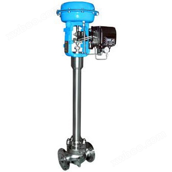
Pneumatic thin film low-temperature regulating valve is a modified product of single and double seat regulating valves. It differs from the ambient temperature regulating valve in that it uses a long necked upper valve cover to keep the packing working at room temperature. apply to-196~-250℃Regulation of media (such as liquid oxygen, liquid nitrogen, etc.) under low-temperature conditions. To ensure adjustment accuracy, it is necessary to usevalvepositioner.
MillerPrecautions for installation and use of pneumatic low-temperature regulating valve:
1. It should be installed vertically on a horizontal pipeline. In special cases where horizontal or inclined installation is required, support should generally be added. The circular board installed on the insulation box wall should be parallel to the insulation box wall.
2It should be installed near the ground or floor for maintenance and repair purposes. For those equipped with valve positioners or handwheel mechanisms, it is even more important to ensure easy observation, adjustment, and operation.
3Generally, a bypass pipeline is set up to switch to manual operation in case of automatic control system failure or maintenance of regulating valves, so as not to stop production.
4When equipped with a handwheel mechanism, manual operation of the bypass pipeline can also be omitted, and it can also be used to limit the opening of the valve. When stopped, the handwheel mechanism must be restored to its original neutral position to facilitate the normal operation of the self-control system.
5During installation, the flow direction of the medium should be consistent with the direction indicated by the valve body.
6Before installing the regulating valve, the pipeline should be cleaned of dirt and welding slag. After installation, fully open the regulating valve, clean the pipelines, valves, etc., and test the sealing of each connection.
Online inquiry
-
Contacts
-
Company
-
Telephone
-
Email
-
WeChat
-
Verification Code
-
Message Content
-