
VIP member

ZX Clear Water Self priming Centrifugal Pump
ZX clean water self-priming centrifugal pump is a self-priming centrifugal pump, which has the advantages of compact structure, easy operation, stable
Product details
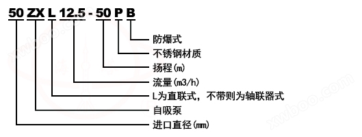
Model meaning
Product Introduction
ZX self-priming centrifugal pump belongs to self-priming centrifugal pump, which has the advantages of compact structure, easy operation, stable operation, easy maintenance, high efficiency, long service life, and strong self-priming ability. There is no need to install a bottom valve in the pipeline. Before operation, only a certain amount of liquid needs to be stored in the pump body, which simplifies the pipeline system and improves working conditions.
application
1. Suitable for urban environmental protection, construction, fire protection, chemical, pharmaceutical, dye, printing and dyeing, brewing, electricity, electroplating, papermaking, petroleum, mining, equipment cooling, oil tanker unloading, etc
2. Suitable for clear water, seawater, chemical media liquids with acid and alkalinity, and slurries with general paste like properties (medium viscosity ≤ 100 cP, solid content up to 30% or less).
3. Equipped with a rocker nozzle, the water can be washed into the air and dispersed into small raindrops for spray. It is a good machine for farms, nurseries, orchards and tea gardens.
4. It can be used in conjunction with any type and specification of filter press, and is an ideal pump for feeding slurry to the filter press for pressure filtration.
condition
ZX self-priming centrifugal pumps all adopt an axial liquid return pump body structure. The pump body is composed of a suction chamber, a liquid storage chamber, a scroll chamber, a liquid return hole, a gas-liquid separation chamber, etc. After the pump is started normally, the impeller absorbs the liquid in the suction chamber and the air in the suction pipeline together, and is fully mixed in the impeller. Under the effect of centrifugal force, the liquid carries the gas to the outer edge of the scroll chamber, forming a white foam belt with a certain thickness and a high-speed rotating liquid ring on the outer edge of the impeller. The gas-liquid mixture enters the gas-liquid separation chamber through a diffusion tube. At this point, due to the sudden decrease in flow rate, lighter gases are separated from the mixed gas-liquid mixture, and the gases continue to rise and be discharged through the pump outlet. After degassing, the liquid returns to the storage chamber and enters the impeller again through the reflux hole. It mixes with the gas sucked in from the suction pipeline inside the impeller and flows towards the outer edge of the impeller under the high-speed rotation of the impeller... As this process continues, the air in the suction pipeline continuously decreases until the gas is sucked out, completing the self-priming process, and the pump is put into normal operation.
Some pumps also have cooling chambers at the bottom of their bearing bodies. When the bearing heats up and causes the temperature of the bearing to rise above 70 ℃, coolant can be injected into the cooling chamber through any coolant pipe joint for circulating cooling. The sealing mechanism inside the pump to prevent liquid leakage from the high-pressure area to the low-pressure area is the front and rear sealing rings. The front sealing ring is installed on the pump body, and the rear sealing ring is installed on the bearing body. When the sealing ring wears out to a certain extent after long-term operation of the pump and affects the efficiency and self-priming performance of the pump, it should be replaced.
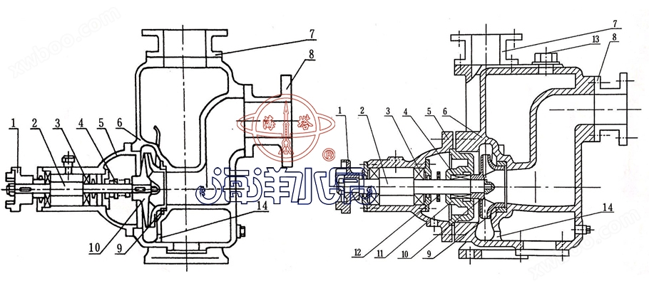
Structural schematic diagram
 |
|||||||||||||
1 |
coupling |
2 |
Pump shaft |
3 |
bearing |
4 |
mechanical seal |
5 |
Bearing body |
6 |
case of pump |
7 |
Exit seat |
8 |
Imported seat |
9 |
Front sealing ring |
10 |
impeller |
11 |
back cover |
12 |
Water retaining ring |
13 |
Add liquid hole |
14 |
Return hole |
performance parameter
model |
Import
|
Export
|
Suction distance
|
electrical machinery
|
internet traffic
|
lift
|
(mm) |
(mm) |
(m) |
(KW) |
(L/min) |
(m) |
|
25ZX3.2-20 |
25 |
25 |
6.5 |
0.75 |
3.2 |
20 |
25ZX3.2-32 |
25 |
25 |
6.5 |
1.1 |
3.2 |
32 |
40ZX6.3-20 |
40 |
32 |
6.5 |
1.1 |
6.3 |
20 |
40ZX10-40 |
40 |
40 |
6.5 |
4 |
10 |
40 |
50ZX15-12 |
50 |
50 |
6.5 |
1.5 |
15 |
12 |
50ZX18-20 |
50 |
50 |
6.5 |
2.2 |
18 |
20 |
50ZX12.5-32 |
50 |
50 |
6.5 |
3 |
12.5 |
32 |
50ZX20-30 |
50 |
50 |
6.5 |
4 |
20 |
30 |
50ZX14-35 |
50 |
50 |
6.5 |
4 |
14 |
35 |
50ZX10-40 |
50 |
50 |
6.5 |
4 |
10 |
40 |
50ZX12.5-50 |
50 |
50 |
6.5 |
5.5 |
12.5 |
50 |
50ZX15-60 |
50 |
50 |
6.5 |
7.5 |
15 |
60 |
50ZX20-75 |
50 |
50 |
6.5 |
11 |
20 |
75 |
model |
Import
|
Export
|
Suction distance
|
electric machinery
|
internet traffic
|
lift
|
(mm) |
(mm) |
(m) |
(KW) |
(L/min) |
(m) |
|
65ZX30-15 |
65 |
50 |
6.5 |
3 |
30 |
15 |
65ZX25-32 |
65 |
50 |
6 |
5.5 |
25 |
32 |
80ZX35-13 |
80 |
80 |
6 |
2.2 |
35 |
13 |
80ZX43-17 |
80 |
80 |
6 |
4 |
43 |
17 |
80ZX40-22 |
80 |
80 |
6 |
5.5 |
40 |
22 |
80ZX50-25 |
80 |
80 |
6 |
7.5 |
50 |
25 |
80ZX50-32 |
80 |
80 |
6 |
7.5 |
50 |
32 |
80ZX60-55 |
80 |
80 |
6 |
18.5 |
60 |
55 |
80ZX60-70 |
80 |
80 |
6 |
22 |
60 |
70 |
100ZX100-20 |
100 |
80 |
6 |
11 |
100 |
20 |
100ZX100-40 |
100 |
100 |
6 |
18.5 |
100 |
40 |
100ZX100-65 |
100 |
100 |
6 |
30 |
100 |
65 |
100ZX70-75 |
100 |
100 |
6 |
30 |
70 |
75 |
model |
Import
|
Export
|
Suction distance
|
electrical machinery
|
internet traffic
|
lift
|
(mm) |
(mm) |
(m) |
(KW) |
(L/min) |
(m) |
|
150ZX170-55 |
150 |
150 |
5 |
45 |
170 |
55 |
150ZX170-65 |
150 |
150 |
5 |
55 |
170 |
65 |
150ZX160-80 |
150 |
150 |
5 |
55 |
160 |
80 |
200ZX400-32 |
200 |
200 |
5 |
55 |
400 |
32 |
200ZX280-63 |
200 |
200 |
5 |
90 |
280 |
63 |
200ZX350-65 |
200 |
200 |
5 |
110 |
350 |
65 |
250ZX550-32 |
250 |
250 |
5 |
75 |
550 |
32 |
250ZX400-50 |
250 |
250 |
5 |
90 |
400 |
50 |
250ZX450-55 |
250 |
250 |
5 |
110 |
450 |
55 |
250ZX400-75 |
250 |
250 |
5 |
132 |
400 |
75 |
300ZX600-32 |
300 |
300 |
5 |
90 |
600 |
32 |
300ZX500-50 |
300 |
300 |
5 |
110 |
500 |
50 |
300ZX550-55 |
300 |
300 |
5 |
132 |
550 |
55 |
install
1. In the direct transmission of pumps and motors, attention should be paid to the coaxiality of the pump shaft and the output of the motor; The accuracy of pump installation has a significant impact on the smooth operation and service life of the pump, so it must be carefully installed and calibrated.
2. The pump coupling must be tightened with a spiral and the nut must be locked to prevent the nut from loosening, otherwise it may cause the impeller to move and cause mechanical failure.
3. In order to maintain a certain amount of stored liquid in the pump body, achieve good self-priming capacity, and prevent dry friction of the mechanical seal, it is necessary to make the inlet of the pump higher than the centerline of the pump shaft.
4. Attention should be paid to the installation of the suction pipeline:
A: The installation height of the suction port should not exceed 3.5 meters. When conditions permit, the installation height of the suction port should be as low as possible below the artificial water storage level of the pool, and the length of the suction pipe should be shortened as much as possible, with fewer bends installed. This is beneficial for shortening the self-priming time and improving self-priming function.
B: Valves, flanges, etc. in the suction pipeline should be strictly guarded against air leakage or liquid leakage, that is, there should be no air leakage in the suction pipeline.
C: Solid and other debris should be prevented from being sucked into the pump body, and a filter should be installed on the suction pipeline for this purpose. The effective flow area of the filter should be 2-3 times the cross-sectional area of the suction pipe, and the filter should be checked regularly
D: The suction and discharge pipelines should have their own supports, and the pump body itself is not allowed to bear the load of the pipelines.
5. When installing the pump, the static grounding resistance of the pump and pipeline should meet its specified requirements.
6. During installation, the static grounding resistance of the pump casing and pipelines should be strictly checked to meet their specified requirements.
7. Correct the installation clearance and coaxiality of the pump coupling and electric coupling. The allowable deviation for different axial degrees is 0.1 millimeters. The height difference between the pump shaft and the electric impeller shaft can be adjusted by placing copper or iron pads on the bottom foot
8. After 3-4 hours of actual operation of the unit, conduct a final inspection. If there are no adverse phenomena, it is considered that the installation is done properly. During the trial operation, the temperature of the bearings should be checked, and the temperature of the bearing body should not exceed 70 ℃.
9. The bearing body of the pump is equipped with a cooling chamber device and a cooling water joint for fitting rubber or plastic pipes with an inner hole of Φ 12, with a thread size of M12 × 1.25.
10. If a one-way valve is installed on the outlet pipeline of the pump and the pump cannot smoothly discharge gas during the self-priming process, an exhaust pipe and valve should be added at the outlet of the pump.
use
(1) Preparation and inspection work before starting;
1. This series of self-priming pumps is lubricated with high-quality calcium based grease and No. 10 engine oil according to the working and operating conditions of the pump. If a grease lubricated pump is used, grease should be regularly added to the bearing box. If a machine oil lubricated pump is used, the oil level should be sufficient.
2. Check if the liquid storage inside the pump casing is higher than the upper edge of the impeller. If it is insufficient, the liquid can be directly injected into the pump body from the filling port on the pump casing. The pump should not be started when the liquid storage is insufficient, otherwise the pump cannot work normally and the mechanical seal may be damaged.
3. Check if there is any jamming or collision of the rotating parts of the pump.
4. Check for loose nuts at the pump body feet and connections.
5. Check the coaxiality and parallelism between the pump shaft and the motor shaft.
6. Check if there is any air leakage in the inlet pipeline, and if there is any, try to eliminate it.
7. Open the valve of the suction pipeline and slightly open (not fully open) the outlet control valve.
(2) TheStart up and operation:
1. Tap the self-priming pump and pay attention to whether the direction of the pump shaft is correct.
2. Pay attention to any abnormal sounds or vibrations during rotation.
3. Pay attention to the readings of the pressure gauge and vacuum gauge. After starting, when the readings of the pressure gauge and vacuum gauge fluctuate for a period of time and indicate stability, it indicates that the pump has been filled with liquid and entered normal infusion operation
4. Before the pump enters normal infusion operation, during the self suction process, special attention should be paid to the increase in water temperature inside the pump. If this process is too long and the water temperature inside the pump is too high, the pump should be stopped to check the cause.
5. If the temperature of the liquid inside the pump is too high and causes difficulty in self-priming, it can be temporarily stopped. The liquid in the discharge pipeline can be used to flow back into the pump or to directly replenish the liquid into the pump through the storage port on the pump body, so as to cool down the liquid inside the pump, and then start it.
6. If there is strong vibration and noise during the operation of the pump, it may be caused by cavitation. There are two reasons for cavitation: one is that the inlet pipe flow rate is too high, and the other is that the suction stroke is too high. When the flow rate is too high, the outlet control valve can be adjusted to increase the pressure gauge reading. If there is a blockage in the inlet pipeline, it should be promptly eliminated; If the suction is too high, the installation height of the pump can be appropriately reduced.
7. The pump stops for some reason during operation and needs to be restarted. The inlet and outlet control valves should be slightly opened (not fully closed) to facilitate the discharge of gas from the outlet during the self-priming process and ensure that the pump starts under lighter loads.
8. Pay attention to checking for leaks in the piping system.
(3) TheStop pump:
1. Firstly, the gate valve on the discharge pipeline must be closed.
2. Stop the pump from rotating.
3. In cold seasons, the liquid stored in the pump body and the water in the cooling chamber of the bearing body should be emptied to prevent freezing and cracking of the components.
Repair and maintenance
The characteristic of this pump is its simple and reliable structure, as well as its durability. Under normal circumstances, the pump generally does not require frequent disassembly and maintenance. Once a malfunction is detected, it can be resolved at any time.
1When maintaining the pump, attention should be paid to several main parts.
A、 Rolling bearings: When the bearings wear out to a certain extent after long-term operation of the pump, they must be replaced.
B、 Front sealing ring and rear sealing ring: When the sealing ring is worn to a certain extent, it needs to be replaced.
C、 Mechanical seal: Mechanical seals should generally not be disassembled for inspection without leakage. If there is a serious leakage at the leakage port at the lower end of the bearing body, the mechanical seal should be disassembled and inspected. When installing and dismantling mechanical seals, they must be handled with care, paying attention to the cleanliness of the mating surfaces, protecting the mirror surfaces of the stationary and moving rings, and strictly prohibiting knocking and collision. The main reason for leakage caused by mechanical sealing is due to the rubbing of the mirror surface. The repair method can be to grind the friction pair end face to restore the mirror surface. Another reason for leakage in mechanical seals is improper installation or deformation and aging of the "○" - shaped rubber seal ring (or buffer pad). At this point, it is necessary to adjust or replace the "○" - shaped sealing ring for reassembly.
2Pump disassembly sequence:
A、 Remove the motor or disconnect the coupling.
B、 Remove the bearing assembly, check the radial clearance between the impeller and the front ring, and check if the impeller nut is loose.
C、 Fold off the impeller nut, pull out the impeller, and check the radial clearance between the impeller and the rear sealing ring.
D、 Loosen the set screw of the mechanical seal, pull out the dynamic ring part of the mechanical seal, check the fit of the dynamic and static ring end faces, and check the sealing condition of the "○" - shaped sealing ring (or buffer pad)
E、 Unscrew the firm nut of the coupling and pull out the coupling.
F、 Remove the bearing end cover and disassemble the bearing of the pump shaft.
G、 Assemble in reverse order during installation.
Common causes and solutions of malfunctions
fault |
cause |
Troubleshooting |
The water pump is not producing water |
1. No or insufficient liquid storage inside the pump casing 2. Air leakage in the suction pipeline 3. The speed is too low 4. The suction distance is too high or the suction pipeline is too long 5. Excessive leakage of mechanical seal 6. The gas in the suction pipeline cannot be discharged from the outlet |
1. Add sufficient fluid storage 2. Check and eliminate any air leaks 3. Adjust the speed 4. Reduce suction or shorten the suction line 5. Repair or replace 6. Let it be expelled |
Excessive noise and vibration |
1. Unstable footing 2. Pump shaft bending 3. Cavitation phenomenon 4. Severe bearing wear 5. There are impurities in the inlet pipeline 6. The main shafts of the pump and motor are not concentric |
1. Reinforcement 2. Replace or calibrate 3. Adjust working conditions 4. Replace 5. Remove debris 6. Adjust coaxiality |
Insufficient water output |
1. The impeller passage and suction pipe are blocked 2. Severe wear of impeller or impeller seal 3. Insufficient power or too low speed |
1. Remove blockages 2. Replace the mouth ring 3. Add sufficient power and adjust to rated speed |
Excessive shaft power consumption |
1. Excessive traffic 2. The speed is too high 3. Bending of pump shaft or collision of impeller 4. The flow channel inside the pump is blocked or stuck |
1. Raise export pressure 2. Reduce appropriately 3. Replace or calibrate 4. Remove blockages |
Online inquiry
-
Contacts
-
Company
-
Telephone
-
Email
-
WeChat
-
Verification Code
-
Message Content
-